Audio Switch
This is the audio switch I am using to mute the receiver when transmitting. When switching to transmit we need to mute the receiver quickly but we want the switch back to receive to be slower. This is to avoid clicks and thumps.
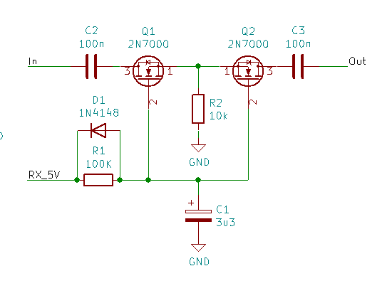
Q1 and Q2 are MOSFETs - these can pass signals regardless of polarity so are great for switching audio. An intrinsic part of a MOSFET is its body diode, as shown in the circuit symbol. This will conduct if the audio signal is loud enough so that any loud click, such as switching between transmit and receive, will still pass through even when the MOSFET is off. The solution is to connect two with the body diodes back-to-back.
Q1 and Q2 will switch on when their gates are sufficiently positive relative to their sources - for the 2N7000 this is about 2V. R2 ensures the sources are at ground potential but its value (10K) is high enough so as not to short the audio to ground.
On RX the control pin (RX_5V) is at 5V and C1 (3.3uF) charges through R1 (100K). C1 will take about 100K x 3.3u x loge(5/(5-2))=168ms to reach 2V and switch on Q1 and Q2.
During TX the control pin is at ground and C1 can discharge through D1 turning off Q1 and Q2 quickly.