CW Key Shaping
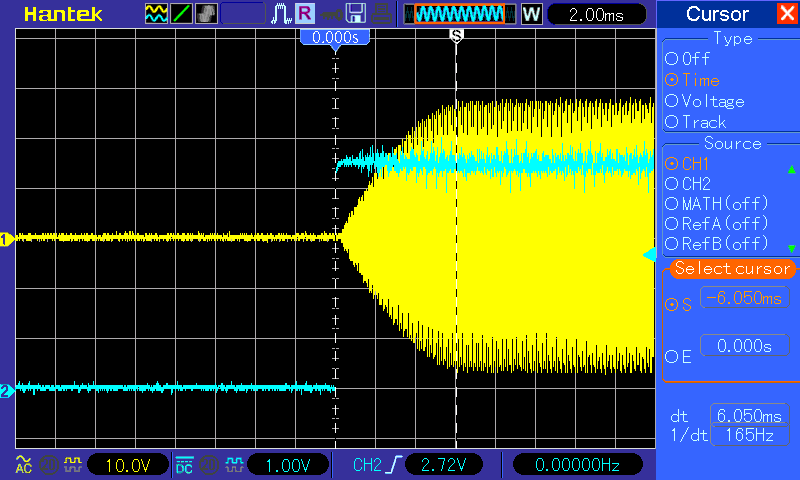
I’ve replaced the 40m Class E PA in my QRP transceiver with a class D amp so that it will work on more than one band (with suitable LPF of course). I had my first two ever 60m CQ QSOs with it at the weekend. I have a key shaping circuit using the same values as in the class E amp but the key up and down transitions were too fast so I changed the component values to increase the delay. I was surprised by the resulting waveform for key down:
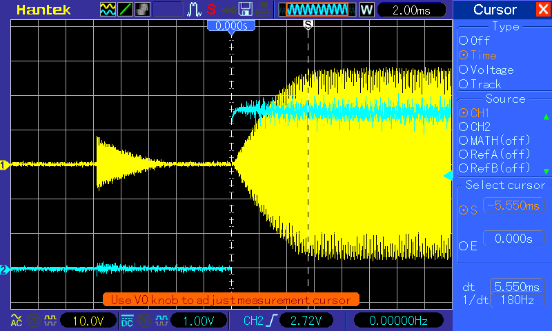
The blue trace is the keying line from the microprocessor and the yellow is the PA output. Before the key goes down there is some output which decays followed by a nicely shaped wave with a transition of around 5ms. But why that initial output? At first I thought that the noise on the keying line was responsible. I then looked at the key up waveform:
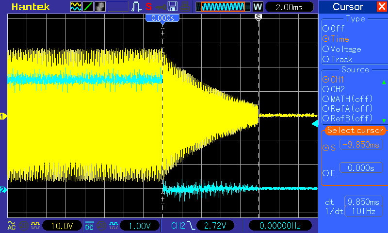
This shows a nicely decaying waveform for about 10ms (a bit too slow) and then it abruptly stops. I wasn’t too concerned about this as some component changes will speed up the transition. The sudden end to the waveform is because 10ms after key up the TX clock is switched off. So I didn’t think much further about key up and continued to ponder the strange key down waveform.
This is the keying circuit but note that the component values will depend on the PA circuit:
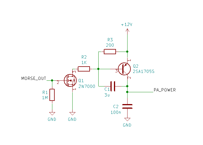
The MORSE_OUT signal from the microprocessor causes Q1 to ground the base of Q2 via R2. Q2 is set up as a Miller integrator - C1 slows the transition in the output. On key up C1 will discharge via R3 and the PA.
I then realised what was happening. On key up, if the TX clock is switched off early C1 will retain some charge since the PA is no longer drawing much current. When the key next goes down this charge will continue to supply the PA explaining the initial output before the key down signal.
Increasing the time that the TX clock is on after key up fixes the problem:
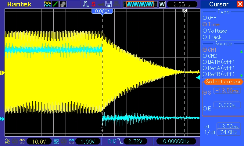
The transitions are too slow but at least I’ve finally understood the problem. I can now work on getting the correct component values.
