Decoupling LCD Displays
In many of my projects I use the ubiquitous 16x2 LCD display. These are available for a few pounds from eBay and other suppliers. They are widely used in Arduino and other hobby projects and so information on how to use them, along with software, is widely available.
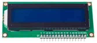
The basic display requires 6 I/O pins (4 data, EN and RS) 1 which can be directly connected to GPIO pins on the microcontroller. But this is a lot of pins to use. My latest project uses an ATtiny85 which only has 5 pins spare (it’s an 8 pin device and VCC, GND and RESET use up 3 pins) so at first sight adding an LCD display was not possible. Fortunately, it is actually possible to add the display without using any additional pins at all. The display is available with an I2C interface (or you can add an adapter board to an existing display). Since I was already using I2C to drive an si5351a clock chip I could add the display without using any more pins.
I’m using the clock chip to drive a Tayloe detector for an image cancelling direct conversion receiver. Every time I changed the frequency I could hear a buzz in the headphones. Investigation proved this was in fact caused by writing to the LCD display rather than anything to do with the clock chip. The back of the LCD board has several unoccupied component positions for capacitors so it makes you wonder whether there is actually any decoupling fitted to the board. I manged to cure the buzz by the addition of two capacitors. It was almost eliminated by adding 1000uF to the 12V input - this drives a 5V regulator for the microcontroller and LCD display. It was completely eliminated by adding 0.1uF (1uF also worked) across VDD and VSS on the LCD module itself. I did also try 100uF on the 12V supply but this only partially helped. Although the 1000uF made a huge difference, the smaller ceramic on the LCD supply was also needed.
I have C drivers for LCD displays (both directly connected and I2C) in my TARL library.
1The LCD module has 11 I/O pins but the RW pin is tied to ground as we never need to read from the display. It has 8 data pins but can be used in a 4 pin mode (this seems to be universal).