Morse Keyer
Update 10/4/2020: I have released v1.1 of the software to set the configuration from EEPROM. See this update.
During these difficult coronavirus times I seem to be as busy as ever. I am lucky enough to still have a job that I can do from home, plus I have two daughters who need help with their home schooling. And the good weather means we are spending lots of time in the garden - it might actually look tidy soon. However, I have decided to do some lockdown projects and here is my first, a morse keyer.
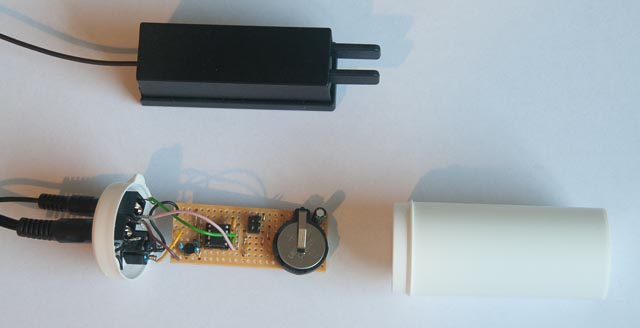
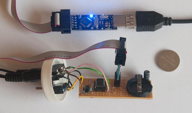
This shows the keyer with its casing - a pill tub (although it probably contained yeast nutrient for beer brewing) and a Palm Mini Paddle.
It is a very simple circuit as it uses an ATTiny85-20PU microcontroller which actually packs in a lot in its 8 pin body costing about a pound. Most of the work is in the software but I had already written a keyer for my transceiver project (which I will publish here one day, but it is continually changing as I tinker) so it didn’t take very long to get this going.
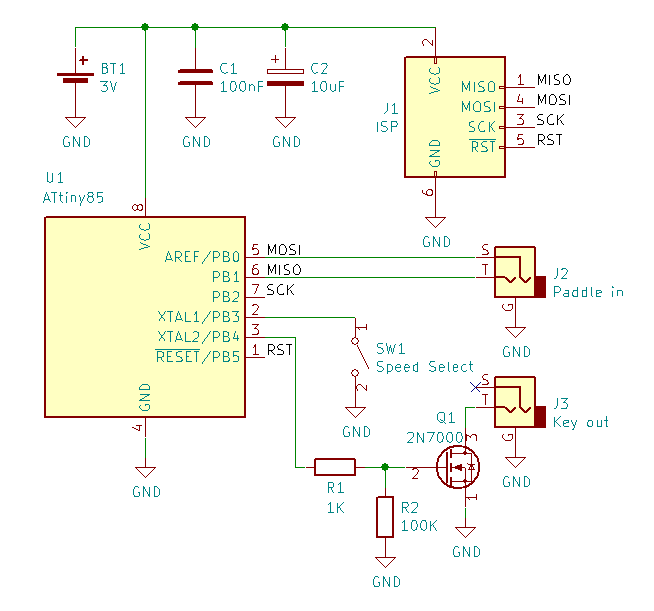
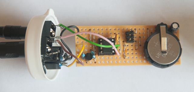
U1 is the ATTiny and it is powered by BT1, a 3V coin cell. I’m using a CR2025 as I have loads of these spare (they come in a pack with CR2032 which are used by a number of household items) but the holder will take any cell with the same diameter. The hardware and software are designed to use as little power as possible (more on this later). If you use an in-system programmer (again, see below) that supplies power make sure you remove the cell beforehand.
C1 and C2 are decoupling and reservoir capacitors. Although the power consumption is very low, U1, like all digital circuits, will draw its current in bursts and these capacitors ensure the supply voltage doesn’t dip. This will become particularly important as the battery discharges and its internal resistance rises. C1 should be placed close to U1. These capacitors should be low leakage types although I found no excess current draw with the two I found in my junk box.
J1 is the header for ISP (In-system programming). This is needed to program the ATTiny. If you have the means to program the chip externally you could omit this, but it makes life a lot easier while developing the software. See later for more on programming.
J2 is a 3.5mm stereo jack socket for the paddle, with the standard wiring of tip for dot and sleeve (or is it ring?) for dash. J3 is a 3.5mm jack socket for keying the transmitter. I’ve used a stereo jack so that I can use a standard lead to connect the keyer to my transmitters which use stereo connectors. You can use a mono jack which actually makes more sense since the transmitters only use stereo connectors as they already contain a keyer in which case why do you need an external keyer?!
SW1 selects the speed from two choices defined in the software. In the current software these are 16wpm and 20wpm but if you want different values then it is easy to rebuild the code. I shall probably make it easier to change these through the EEPROM in a future version of software.
R1, R2 and Q1 form a switch to ground the key out line and hence key the transmitter. Q1 is a 2N7000 MOSFET but almost any N-channel device could be used here. If you are using the keyer with an old valve transmitter you will need to choose a device that can handle the voltage on the key line. R1 and R2 are not strictly necessary but R1 limits the current if there is a fault in Q1 and protects U1. R2 guarantees that Q1 is off if the power is disconnected (a MOSFET’s gate will hold its charge otherwise).
ATTiny85-20PU
The ATTiny is part of the AVR family of microcontrollers - the ATMega is the more powerful version used in the Arduino. There is a huge range of ATTiny chips available and it isn’t necessary to use exactly this chip. This has 8K of flash, 8 pins and runs at up to 20MHz. The software uses the default internal 8MHz RC clock so a slower version would be fine. The code is just over 2K (and could easily be made smaller) so you could use the 4K or 2K versions. However, in single quantities, there is hardly any difference in price so just use whatever is easy to get hold of.
Many keyers use PIC microcontrollers but I chose the AVR family for a number of reasons. As the ATMega is used in the Arduino it is easy to get cheap boards and I use an Arduino Nano clone in my transceiver. The code can be transferred across to the ATTiny with very few changes (the hardware registers for timers, IO ports etc are pretty much identical). I was also under the impression that it is hard to program the most basic PIC controllers in C rather than assembler but I concede that this may not be accurate. Microchip (who designed the PIC) bought Atmel (who designed the AVR family) so I can’t help thinking that the PIC developer agrees with me that the AVR is better! Or at least they see it as serious competition.
Software
I have released the source code under the GPL at github. It is built using Atmel Studio 7 which is only available for Windows. I will add Linux builds soon. Instructions for how to build and how to change configuration are with the source at Github.
There are also pre-built hex files ready for programming the ATTiny - there are versions for Iambic A, Iambic B and Ultimatic. The two speeds supported are 16wpm and 20wpm. These hex files are available under the Releases tab.
For the source code you can either download a zip file of a release or clone the git repository.
Note that I may change the software so there is only one version - the release notes will give details.
Programming
To program the ATTiny via the ISP header I use a USBasp programmer which is very cheaply available (about £3). Note that this has a 10 pin header so I also have a 10 to 6 pin adapter. It’s also possible to use an Arduino for the programming - instructions are easily found on the web.
The application that drives the programming hardware is avrdude which is a command-line program but it’s much easier to use a GUI front end. It’s easy to set up Atmel Studio to use avrdude (which is very useful while you are developing the software) or you can use avrdudess if you just want to program the hex file.
There is no need to change any of the fuse bits.
Note that you must remove the battery cell when using the programmer (assuming it supplies power). It is fine to use a 5V programmer.
Power consumption
There is no on/off switch so it is important that the design draws as little current as possible. My measurements are 800uA while sending and less than 2uA while idle. A CR2032 cell is about 200mAh so in idle it should last around 100000 hours which is around 11 years!
To achieve this low power consumption in idle the software puts the ATTiny into power down mode shortly after the last dot or dash is sent. This shuts down almost everything on the chip and it is woken by a pin-change interrupt on the dot and dash paddle pins.
When I first built the keyer I used a potentionmeter connected to an analogue input pin as a speed control to allow any speed to be set between, say, 10 and 30wpm. This has two power problems. One is that the A/D converter uses around 400uA so it massively increases the consumption during use, although it’s possible to switch this off in power down mode. But putting a 47K pot across the 3V battery draws around 64uA even in idle mode which is clearly unacceptable. One way round this is to connect the pot between an output pin and ground and turn off this pin in power down mode. Although this isn’t too hard I decided for simplicity to just offer two speeds. I tend to use 16wpm for rubber-stamp and rag chew QSOs and 20wpm for DX/special event/contest stations. If I call someone working at a lower speed I just increase the gaps between characters.