RF Changeover
I’ve been playing about with simple transmitters and receivers. The former are easy - a crystal oscillator, PA and key shaping circuit. But receivers are much harder so I’ve been using my existing Arduino based direct conversion receiver. This means I need a way to switch the antenna between RX and TX so I’ve built an RF sensing changeover circuit.
This circuit is originally from the book QRP Basics (2nd Edition) by the late, and much missed, Rev George Dobbs G3RJV.
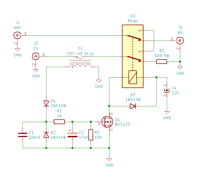
Normally the antenna is connected through the relay to the receiver. The transmitter is connected to a 50R resistor adequately rated for the transmitter power - it’s effectively a dummy load but shouldn’t actually be connected to the TX for long. The transmitter is connected to the relay by a wire through a T37-43 toroid forming the primary of a transformer. The secondary is 5 turns of suitable wire - I used 30SWG enamelled. This feeds to a diode detector (actually a voltage doubler) to switch a MOSFET to energise the relay to connect the transmitter to the antenna. To prevent the relay from chattering with the morse keying (or during speech pauses) C2 holds the MOSFET on for a period (determined by R2) to give semi-break in keying.
I used a 12V surface mount relay as that suits my standard 12V (or 13.8V) power supplies. In the original circuit the MOSFET was a VN10KLS which are now obsolete. I used a surface mount BSS123 but most small signal MOSFETs should work here, provided the gate threshold isn’t too high. R3 is two 100R resistors in parallel.
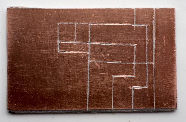
I used surface mount components as much as possible but I didn’t have everything so used bigger through hole types for everything else. I used a small piece of copper clad board dividing the copper surface into areas with a tile scriber.
After building the circuit board I gave it a test. I’m pleased to say it worked really well with my little 1W transmitter into a dummy load. As you can see the 12V relay works just as well with a 9V battery.

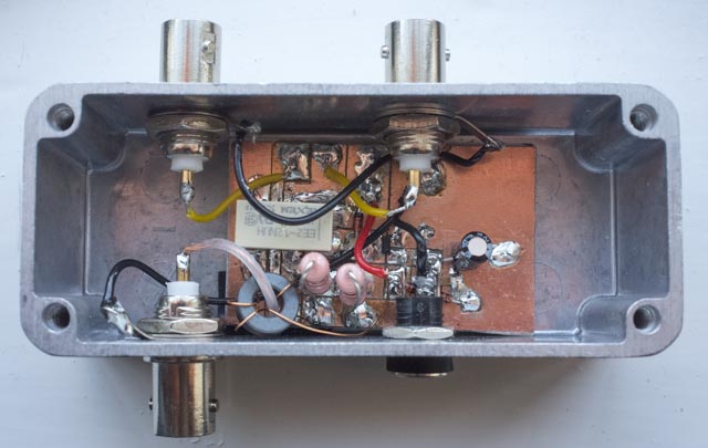
Here’s the finished circuit in its box. I put the power socket opposite the receiver socket so that I could ream the holes to the right size - the box is too narrow for the reamer to go in the hole far enough, unless there is a hole the other side.
It doesn’t provided perfect isolation between the receiver and transmitter - the transmitted signal is still audible in the receiver but it isn’t unbearably loud and works perfectly as a sidetone.