Direct Conversion RX Isolating Preamp
My direct conversion transceiver works very well on 40m but when I converted it to work on 20m I found that it suffered from an annoying hum. This is a very common problem with direct conversion receivers due to local oscillator leakage and is more likely on the higher bands. The usual cure is to add filtering to the power supply. As the hum was still there when powered by a battery this was not a solution for me.
A quick check with a ‘scope showed that the local oscillator was indeed leaking out despite using a double-balanced mixer. So the solution was to somehow reduce that oscillator leakage. The circuit shows a preamp that I used to isolate the oscillator from the antenna. It has completely cured the hum on 20m.
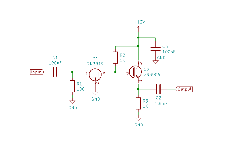
C1 and C2 are coupling capacitors to isolate DC. C3 decouples the power supply.
Q1, R1 and R2 form a common-gate amplifier. I chose this as it has low input impedance which is easy to match to the 50 ohm input. It also provides good isolation between input and output and so is ideal for this application.
The input impedance of the common gate amplifier is formed from R1 in parallel with Q1’s input impedance. For a JFET this is 1/gM where gM is the forward transconductance. For the 2N3819 this is around 5mS (millisiemen which is 1/ohm). So 100 ohm (R1) in parallel with 200 ohm gives about 70 ohm. This is very close to 50 ohm and could be brought nearer but, with component tolerances etc, this is likely to vary from sample to sample.
The output impedance of the common gate amplifier is given by R2 i.e. 1K. This is too high to match to the receiver input of 50 ohm. Why not reduce R2 to reduce it? Because the gain is given by Av = gM(R2||RL) = 5 x 10-3 x 25 which is very low. (RL is the load impedance).
So I have added Q2 and R3 to form an emitter-follower with high input impedance (ZI) and low output impedance (ZO).
ZI = ~βRE = ~βR3
Q2 is a 2N3904 which has fT of 300 MHz so at HF, with a maximum frequency of 30MHz, β>10. Hence ZI>10K. This is much higher than R2 so AV = 5 x 10-3 x 1000 = 5.
For the emitter follow ZO = ~Zsource/(β + 1) = 1000 / 9 = ~100 ohm
The voltage gain of an emitter follower is ~1 so the overall gain is about 20 log10 5 = 14dB. Since the output impedance is higher than 50 ohm the gain will be lower.
I tested the preamp with my nanoVNA. Throughout the HF range it has a return loss of about 15dB so is well matched to 50 ohm. The gain varies from 10dB at 2MHz to 3.5dB at 28 MHz. At 14MHz it has a gain of 7.5dB. Most importantly it has completely eliminated the hum.