5 Band CW QRP Transceiver Clock and Control Board
Part of the 5 band transceiver.
The clock and control board is the heart of the transceiver containing the ATtiny 3216 microcontroller and Si5351A clock generator chip. It generates quadrature clocks for the
Tayloe detector in the receiver and the transmit clock for the class E PAs. It also controls the display, morse keyer, transmit/receive switching and so on.
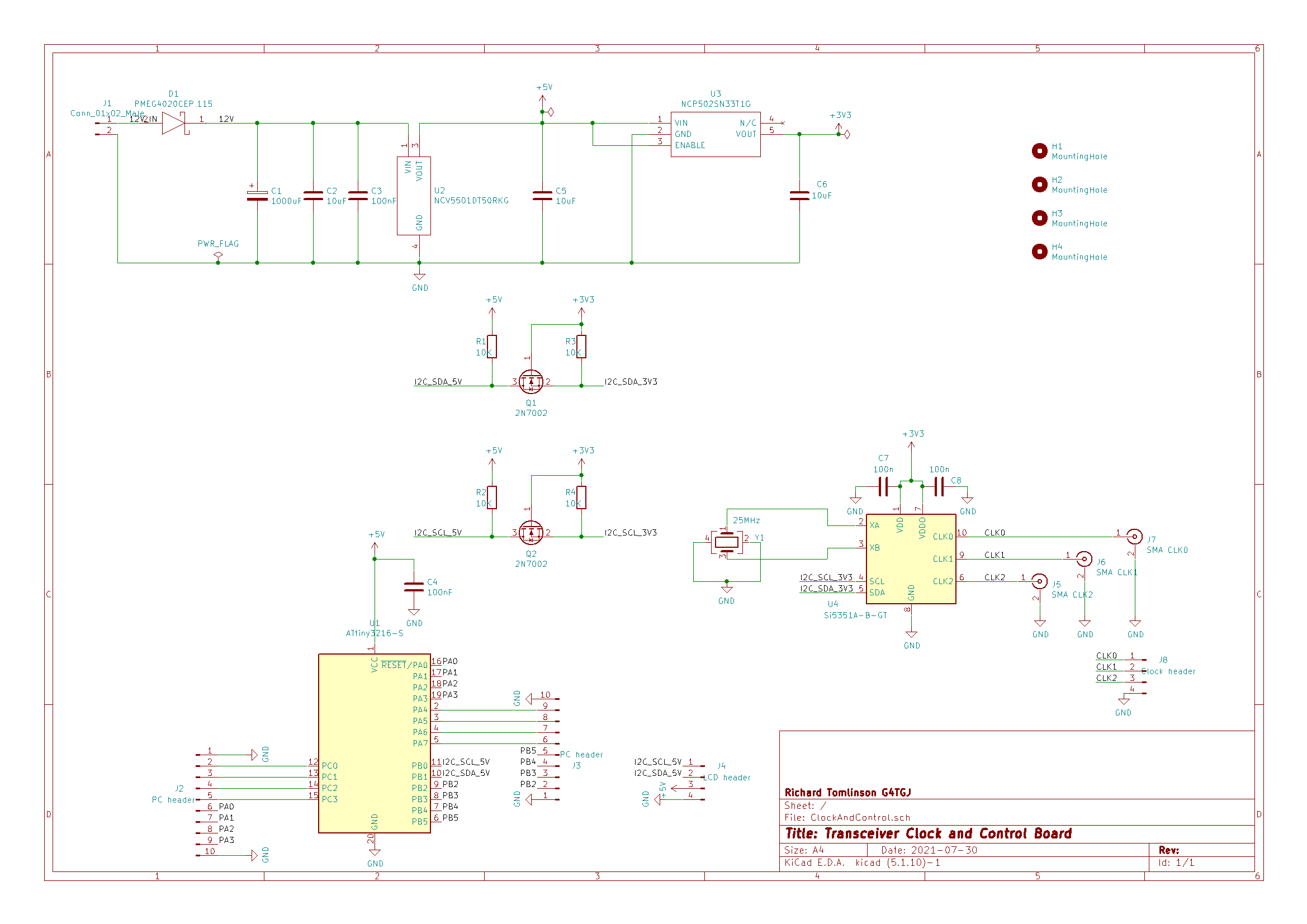
J1 takes 12V in, D1 protects against reverse polarity, U2 is a 5V regulator (for the microcontroller and LCD) and U3 is a 3V3 regulator for the clock chip. Q1 and Q2 are bidirectional I2C level shifters to convert between 3V3 and 5V. The ATtiny3216 can run at 3V3 but the LCD requires 5V.
J2 and J3 are pin headers for most of the I/O pins on the microcontroller. See below for where they connect. J4 is for the LCD taking 5V and the I2C bus.
J5-J7 are SMA sockets and J8 is a pin header for the 3 clock outputs. I only use J8. CLK0 and CLK1 connect to the direct conversion receiver board and CLK2 goes to the TX boards.
| Pin | Function |
|---|---|
| PA0 | UPDI (Rear panel update socket) |
| PA1 | Serial TX (Rear panel CAT port) |
| PA2 | Serial RX (Rear panel CAT port) |
| PA3 | Sidetone (Phasing audio filter and amplifier board) |
| PA4 | Morse paddle dash (Front panel paddle socket) |
| PA5 | Morse paddle dot (Front panel paddle socket) |
| PA6 | Transmit (TX boards) |
| PA7 | Receive enable (Phasing audio filter and amplifier board) |
| PB0 | I2C SCL (LCD) |
| PB1 | I2C SDA (LCD) |
| PB2 | Relay 4 (20m TX board) |
| PB3 | Relay 0 (80m TX board) |
| PB4 | Relay 1 (40m TX board) |
| PB5 | Relay 2 (30m TX board) |
| PC0 | Pushbuttons (Front panel) |
| PC1 | Relay 3 (60m TX board) |
| PC2 | Rotary encoder A (Front panel) |
| PC3 | Rotary encoder B (Front panel) |
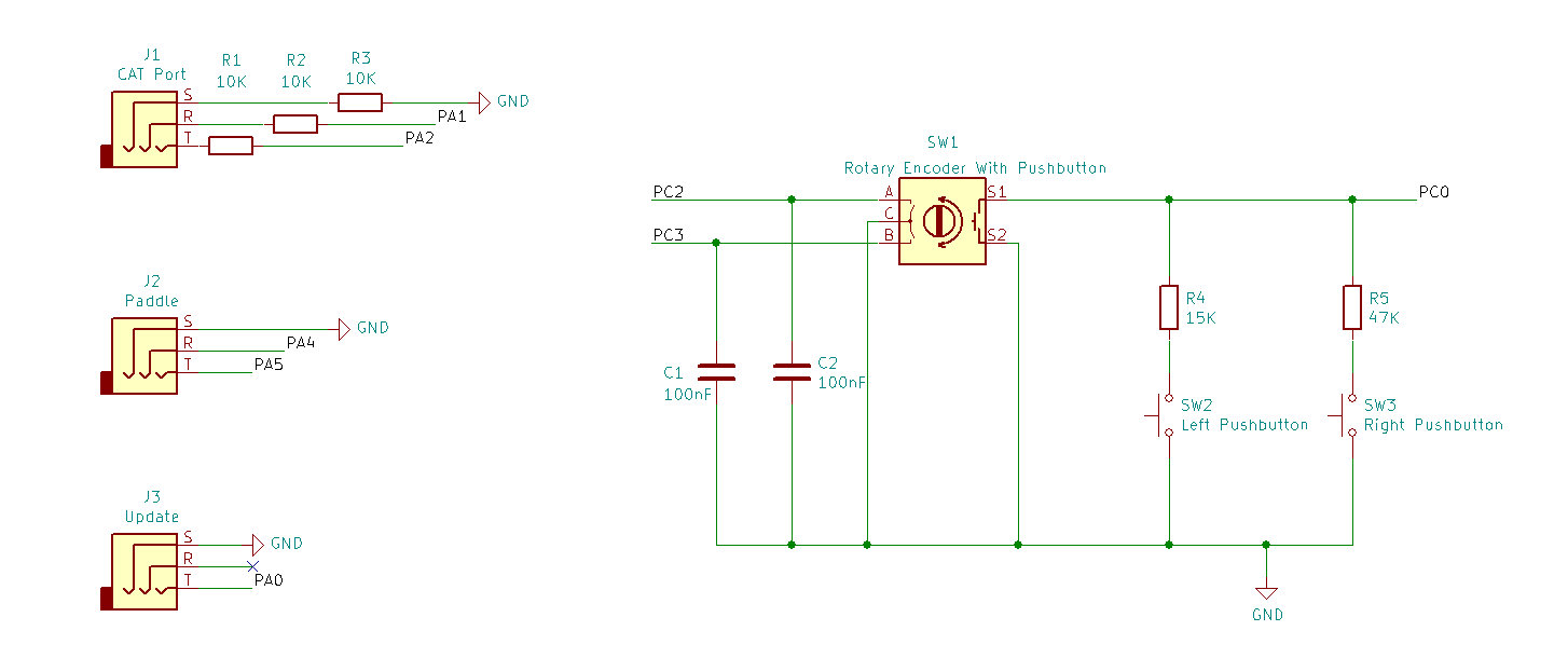
I found that connecting to my PC’s serial port with a cheap USB serial adapter introduced a lot of noise into the receiver. The proper solution would probably be to use an opto isolator but I found that adding 10K resistors to the connection cured it. Even the earth connection was noisy.
The three front panel pushbuttons are connected to PC0 configured as an ADC input.
Next article - Direct conversion receiver block