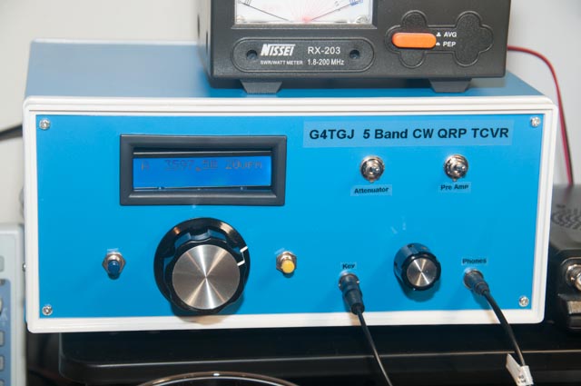
5 Band CW QRP Transceiver
I’ve been working on a homebrew QRP CW HF transceiver for some time. It was originally based around an Arduino Nano but now uses an ATtiny3216. Features include:
- Image cancelling direct conversion receiver with Tayloe detector
- Full microprocessor control with stable Si5351A oscillator
- 80m/60m/40m/30m/20m
- Full break-in
- Switchable front-end attenuator and pre-amp
- Selectable tuning steps
- Separate TX board for each band with class E PA and LPF
- 5W output
- CAT control
- Output for an external SDR receiver
- Internal morse keyer supporting Iambic A and B and Ultimatic
- Open source software
I will write it up in a series of posts here. If you would like PCB layouts, the Kicad files or help with the software then please get in touch.
Overview
The transceiver is built on a series of surface mount boards:
- Clock and control board contains the microcontroller and oscillator chip
- Direct conversion receiver block contains the TX/RX switch, splitter for the SDR output, switchable attenuator and pre amp, Tayloe detector and amplifier
- Phasing audio filter and amplifier board has op-amp active filters for 90 degree phase shift for image cancellation, 200Hz CW filter and headphone amplifier
- Transmit board for each band contains a MOSFET driver, IRF510S class E PA, key shaping circuit, low pass filter along with a relay to switch the board in and out of circuit
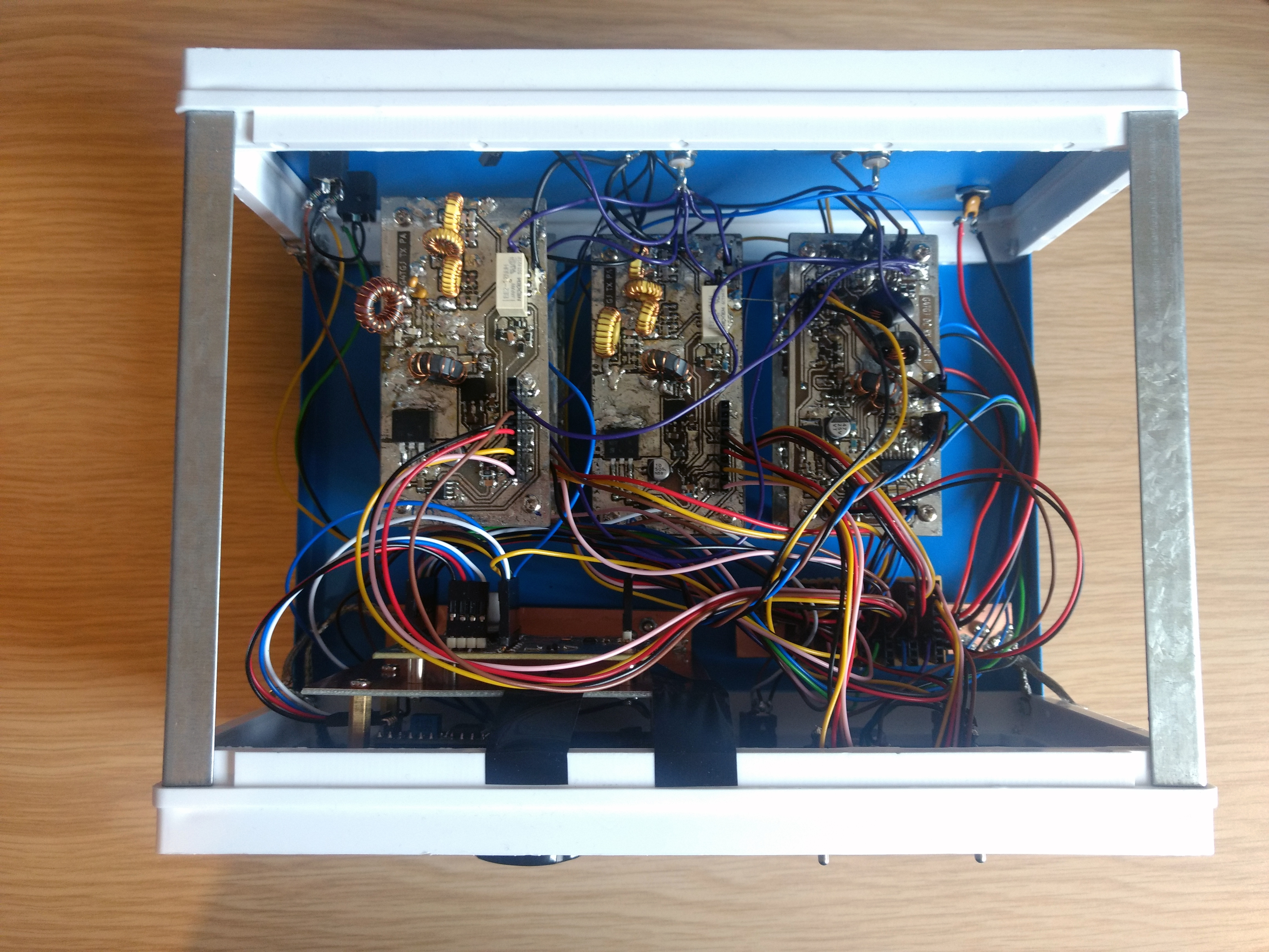
The interconnections between each board are mostly with pin headers although some of the RF interconnections for the higher bands are directly soldered. The TX boards are effectively connected through a bus with each board having its own enable signal.
The rotary encoder is 24 pulses per revolution with 0 detents. Unfortunately the best large knob I could find is spline fitting but the encoder is D shaped so I had to make it fit. But the tuning is nice and smooth.
Each board is fed with 12V from the power input connector. If a board needs a lower voltage then it has its own voltage regulator (the clock and control board has two as it needs 5V and 3V3).
CAT control and SDR output
I use it with my SDRPlay RSP1a with SDRUno on the PC as the panadapter. The CAT control allows me to click on a signal on the waterfall and the rig tunes to that frequency. As it uses Omnirig it also works with Log4OM. It simulates the FT450D as I have one of these for comparison.
Case
The case is “25x19x11CM Metal Electronic Enclosures Box Projects Switch Junction Case Cover”. These were widely found on online marketplaces but don’t seem to be any more which is a shame. It’s a great value case for this sort of project. There is no continuity between the metal panels so I used braid from RG58 coax to improve this. My mounting arrangement for the LCD isn’t great as you can see from the use of tape in an attempt to pull it back towards the front panel. The panel flexes a bit which does not help.
Software
All the software is open source and hosted at github. The software is still a work in progress but works and is quite stable. It makes use of TARL which is a library of AVR source code for radio projects.
Next article - Clock and control board
There is also a two band portable version for SOTA - Two band SOTA transceiver