Two Band CW QRP SOTA Transceiver
Based on the 5 band transceiver.
My original motivation for home brewing a transceiver was for SOTA activations. I’d been using an FT817ND very successfully but found it awkward to use
with an external CW filter and battery plus the Yaesu’s form factor isn’t all that convenient when sat on a hilltop. I had built a 30m QCX kit so knew it
was possible to build a high performance CW rig. This finally led to my 5 band transceiver
but that’s a base station so I needed a portable version. For
SOTA 40m and 20m give good European coverage plus the chance for some DX.
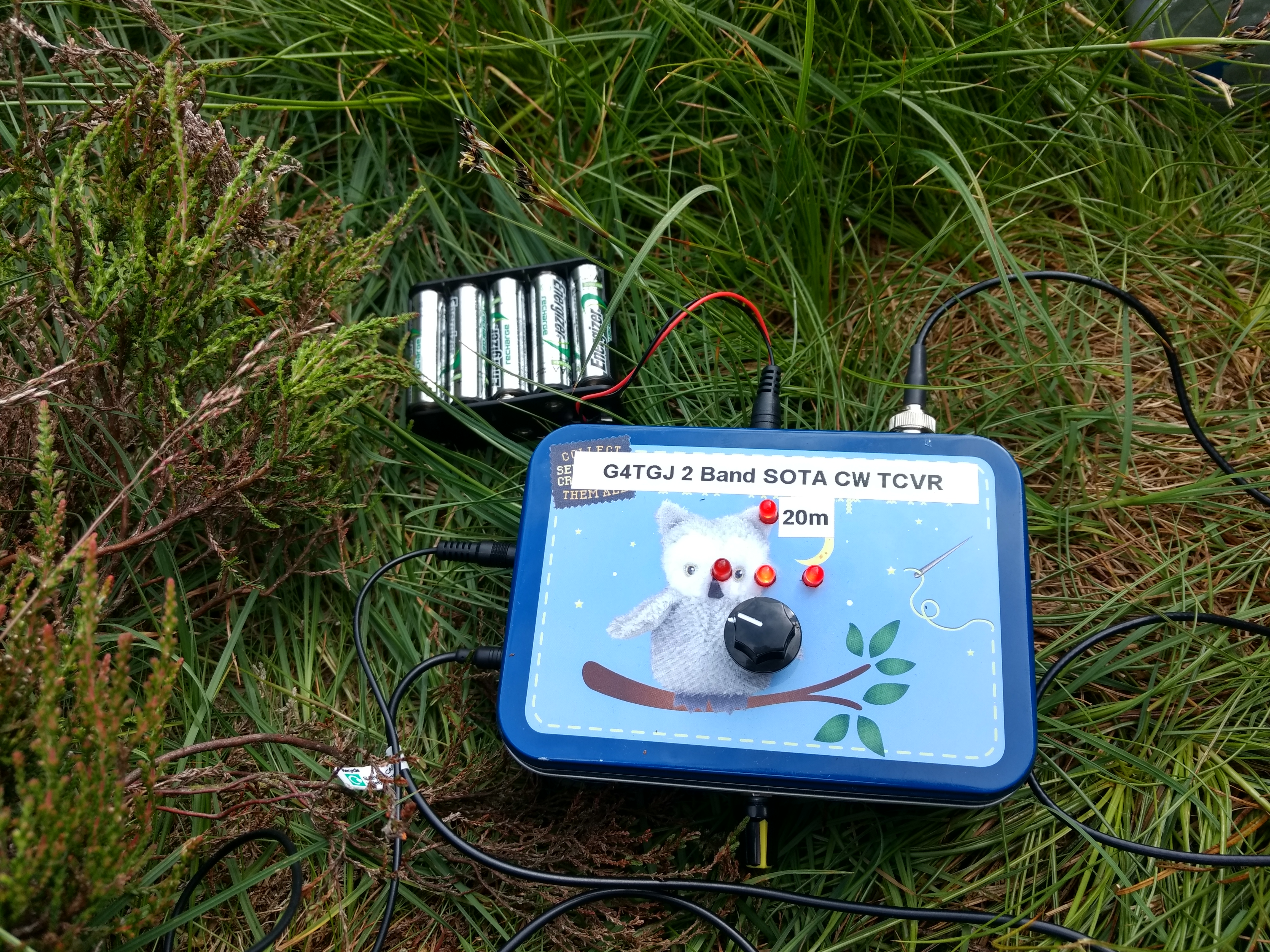
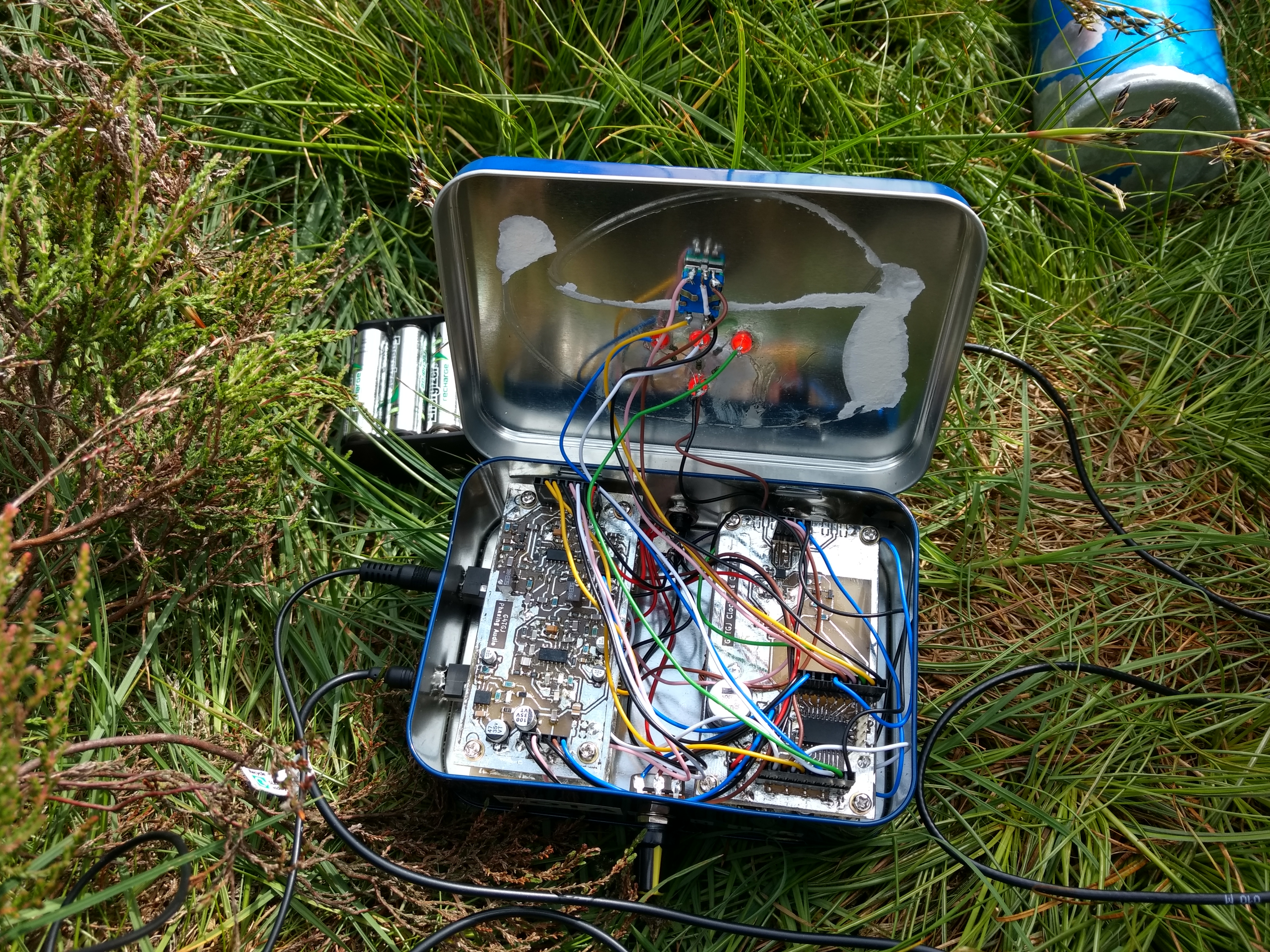
I decided to simplify the user interface and do without an LCD screen. I had a tin that was a “Gift in a tin” sewing kit that one of my daughter’s had
finished with. I realised I could just about fit 4 of my transceiver PCBs in so all I had to do was produce a two band transmit board and a SOTA in a tin
transceiver was possible.
Most SOTA activations take place near to the QRP centre frequencies. I always find a clear frequency near there to call CQ. Thanks to the Reverse Beacon Network the CQ should appear very quickly as a SOTA spot and you will get a nice little pile up. Because of this I decided that a simple interface would work quite well.
Instead of an LCD screen the rig has 4 LEDs. The top LED lights when 20m is selected, otherwise it is on 40m. The three LEDs above the rotary control show where in the band you are. The centre LED lights to show you are on the initial frequency which is the QRP frequency of 7030kHz or 14060kHz. Each click of the control is 100Hz so it’s fairly easy to know what frequency you are on. As you tune up in frequency the right LED also lights. When you are 10kHz away from the start frequency the centre LED goes out. A short press of the rotary control takes you back to the start frequency. A long press changes band. If you were to tune all the way to the band edge then all 3 LEDs light and the rig won’t transmit.
The rig uses the same clock and control board and the same audio phasing board as the 5 band transceiver. I used an earlier version of the direct conversion receiver block. It is the same circuit but without the switchable attenuator and preamp and without the splitter. To build it simply connect the the drain of Q4 to the top of L2 and omit all the components inbetween. [EDIT: This is the original DC receiver block that I actually used.]
The transmit board contains the class E network and LPF for 20m and 40m switched by a relay. The board is very similar to the existing transmit board.
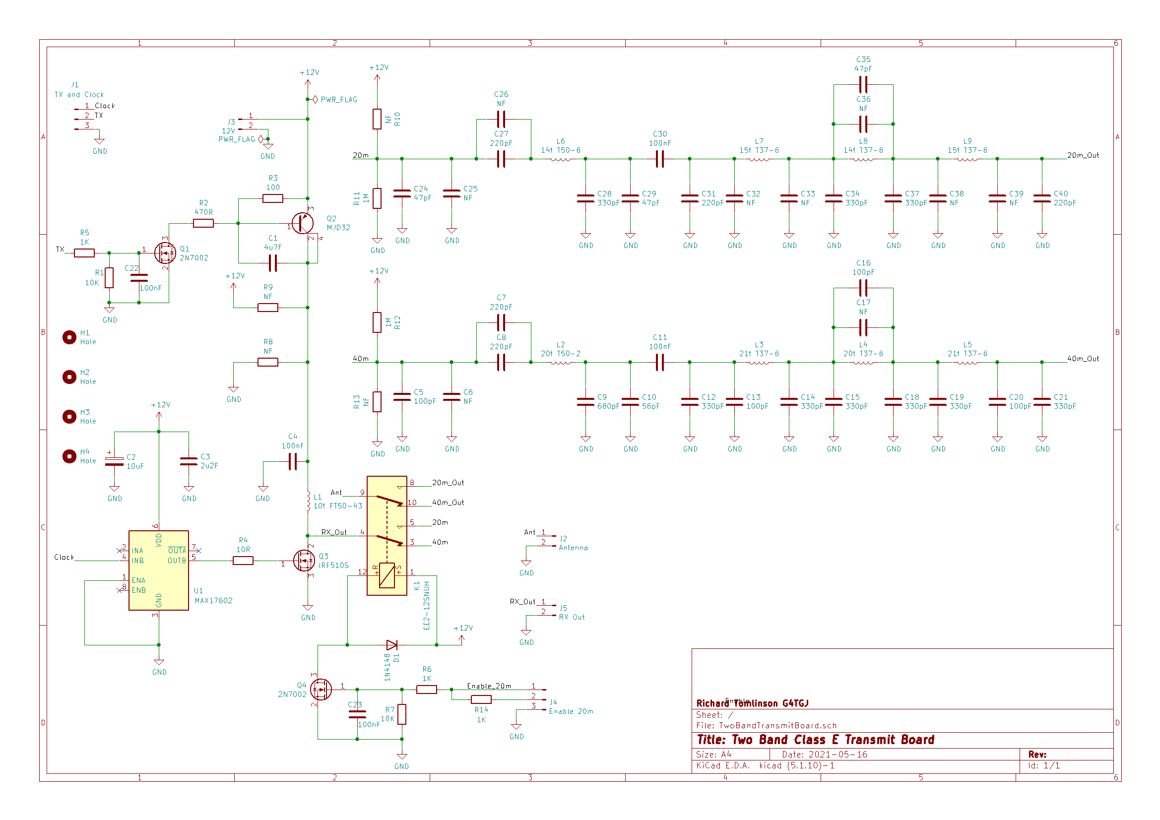
By default the board is enabled for 40m. If the Enable 20m line is high then Q4 engages the relay and the relevant class E network and LPF is used. Also the band LED is connected via the current limiting resistor R14 so that it lights when 20m is selected.
Interconnections from the clock and control board:
| Pin | Function |
|---|---|
| PA0 | UPDI (For software update) |
| PA3 | Sidetone (Phasing audio filter and amplifier board) |
| PA4 | Morse paddle dash (Paddle socket) |
| PA5 | Morse paddle dot (Paddle socket) |
| PA6 | Transmit (TX board) |
| PA7 | Receive enable (Phasing audio filter and amplifier board) |
| PB2 | Right LED (Top panel) |
| PB3 | Centre LED (Top panel) |
| PB4 | Left LED (Top panel) |
| PC0 | Rotary pushbutton (Top panel) |
| PC1 | 20m Enable (TX board) |
| PC2 | Rotary encoder A (Top panel) |
| PC3 | Rotary encoder B (Top panel) |
There is a different software build for the SOTA transceiver. Ready built hex files are also available - see the releases tab to the right.